Laser scanning using a laser pointing device and a camera
The method is (usually) based on triangulation.
This means that a triangle has to be formed, having the camera, the laser device and
an unknown point as vertices. Using the law of sines,
one can calculate the distance from the unknown point, thus resolving the 3D
geometric problem.
Here is how this can be done:
Fig. 1. The process of triangulation for an
unknown point in 3D space
The baseline distance between the camera and laser
diode is denoted by d, while φ is the angle of the camera and θ
the angle of the laser both with the axis vertical to the line that connects
them. In total, the variables that are the known parameters of this arrangement
are (for a pinhole camera model):
- The camera field of view (angle, FOV)
- The camera frame resolution, i.e. the frame width w and the frame height h
- The relative topology of the arrangement, i.e. the camera and laser angles φ and θ and the distance between them (d)
- The key value of the camera focal length can be deduced from the known parameters:
 |
(1) |
Triangulation is based on the law of sines,
which states that if the sides of an arbitrary triangle are a, b
and c and the angles opposite those sides are A, B and C:
|
|
(2) |
where R is the radius of the triangle circumcircle.
In the described case, (2) becomes:
|
(3) |
In this topology the problem is a typical geometric problem that can be easily
solved, as:
|
(4) |
and, as of this, the unknown distance from the camera
is:
|
(5) |
The only unknown variable here is the angle φ, which can easily be
estimated trigonometrically:
|
(6) |
In practice, it is more convenient to estimate the X,Y,Z
coordinates of the detected point instead of its distance from the camera t.
This can be achieved if instead of working with the distance s we
estimate angles in X and Y axis separately. The notion is depicted graphically
in Fig. 2, where the detection angle dφ is represented by two angles
that are relative to one axis, i.e. dφX for X and dθY
for Y.
Fig 2. A more practical approach to the estimation of the unknown coordinates of a detected point
The estimation of these angles is equivalent to the estimation of dφ in (6). The final equations are:
|
(7) |
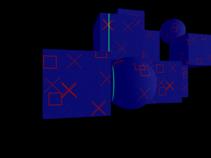
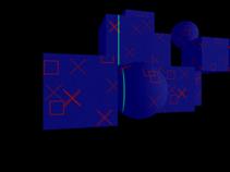
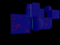
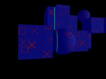
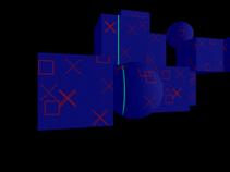
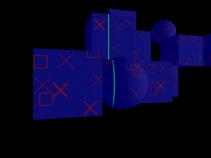
A practical example of the triangulation process
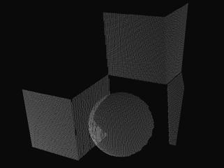
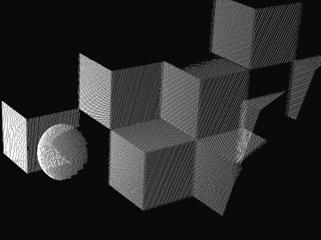
In the following images, a portion of a scanning sequence is shown (Fig. 3). The laser device projects a line on the objects of interest and an image is captured in the camera at every time interval. The detected laser light is then processed pixel-by-pixel in order to deduce the geometry of the objects (Fig. 4).
 1 1
|
 2 2
|
 3 3
|
 4 4
|
 5 5
|
 6 6
|
Fig 3. Six (1 to 6) consecutive images (with step two images) from the test data set. The
green line is the laser projected on the object.
|
|
Fig 4. The result of the digitization process (point cloud) at different time intervals.
